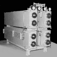
CO2-Toluene Whole Core
Cleaner


Model 920
CO2-Toluene
Whole Core Cleaner
The Model 920 CO2-Toluene Whole Core Cleaner
is a system to clean crude oil, water, and drilling mud liquids from whole core
samples in preparation for porosity and permeability measurements. The core is first saturated with CO2
and then with solvent (toluene) forcing the gas into solution. The cores are heated above the boiling point
of water and when the pressure is reduced, the dissolved CO2 will
drive the solvent and the core liquids from the rock pore space. The process was developed and patented in
the 50's by Stanolind Oil Company, now know as Amoco Production Company. The development was an outgrowth of their
pressure depletion gas drive production research.
The
whole core cleaning system is constructed in two parts, the core cleaning cells
and the fluid handling unit.
Cells
The cells are assembled and
plumbed in pairs. The 12cm (4.75
inches) inside diameter cells are suitable for cores drilled in most of the
world and a larger version, 15 cm (6 inch) diameter, primarily for cores drilled
in the North Sea, is available. The
standard length for both sizes is 236 cm
(93 inches) inside for an overall
length of 2.4 m (8 feet). Steam
jackets, common to each pair, provide the cell heating mechanism. As few as two and as many as eight cells can
be mounted together and supplied by the Fluid Handling Unit. The cell skid comes plumbed complete with
valves, gauges, and relief valves.
Fluid Handling Unit
The fluid handling equipment is
all mounted on one skid. There are
tanks for the clean and used solvent, and a solvent recovery still. The solvent recovery still consists of a
stainless U-tube reboiler, liquid-gas disengagement area, and condenser. The still will recover about one gallon/minute.
A cyclone separator and
water-cooled after-cooler are used to separate the hot solvent and CO2
returned from the cleaning cells when they are drained. An outside vent is required downstream from
the after-cooler.
Controls
The fluid handling system is
self-sufficient with the exception of having to replenish the clean solvent
that is lost out the stack or through spillage.
The solvent recovery still is
automatic. A process controller and an
annunciator panel are enclosed in a NEMA-4 box, located outside of the
hazardous environment. The system may
be operated in automatic or manual mode.
The process of filling the cells with CO2 and solvent, and
draining is controlled by the process controller in automatic mode.
Operation
The system is operated in the follow manner. Trays are provided to hold the core in the cells.
1.
Load all of the cells that are to be used.
2.
On the control panel, select the NUMBER of pairs of cells
that have been loaded (1,2,3,4).
3.
Select the duration of the cleaning cycle SHORT (4 hours) or
LONG (12 hours), and AUTOMATIC/START.
The process controller operates the system by first opening the steam
valve providing heat to the cell jackets.
Air is purged from the cells using
CO2, then the cells are charged to about 1400 kPa (200 psi) with CO2. The cells are then filled, against a closed head,
with solvent forcing the gas into solution and saturating the rocks. After a suitable soak time the cells are
drained and the cycle repeated. At the
end of the cleaning process, the cells are again drained and the steam that
heats the cells is turned off.
Options
Cell ID: 12 cm (4.75") ID is
standard, 15 cm (6.0") ID is optional.
Control
panel: NEMA-4 enclosure is standard,
explosion proof is optional. An
explosion proof room with ventilation that sweeps vapors from the floor is
recommended as a suitable enclosure. A floor drain with an 60-gallon minimum
capacity oil trap is also recommended.
CO2 in combination with toluene and at elevated temperature
is difficult to contain. Teflon seals
are used throughout to help minimize leaks.
The user supplies CO2, toluene, steam (a minimum of 45 kg at 240 kPa
(100 pounds/hour at 35 psig)) regulated to 5-25 psig at the cell steam jackets
and 35-40 psig at the recovery still, cooling water (40 l/m at 140 kPa (5 gpm @
20 psi) minimum), and 230-volt, single phase, 5-amp service.
Go to Harbert Engineering Homepage